Dear Prof. Masin and Soil Model Community,
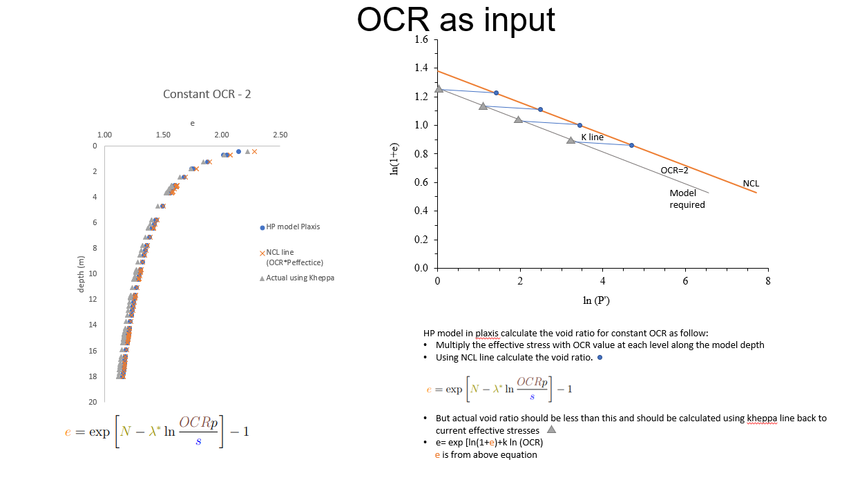
I am using HP clay subroutine in Plaxis 3D to simulate soil structure interaction problem. I want void ratio and OCR variation along the depth to back analyse centrifuge test. In Plaxis, either or OCR remains constant depending on input. Moreover, I found HP subroutine in plaxis calculate void ratio without considering kheppa line. Please see details and explanations in the attached images. My objective is to obtained initial void ratio and OCR variation along the model depth. Also, I want to confirm the position of e input in parameters in ln(1+e) – lnp space. Thanks
HP clay subroutine in Plaxis
Related Articles
-
In Abaqus how do we use *DLOAD for defining both user-defined pressure and body force simultaneously?
Ashesh Choudhury||Finite Elements|0 |Views 1,436
In Abaqus how do we use *DLOAD for defining user-defined pressure and body force simultaneously? I want to user-define both body fore and pressure. -
Tochnog Professional overview movie in youtube
Dennis Roddeman||Finite Elements|0 |Views 4,108
Dear All, We posted a small overview movie of Tochnog Professional in YouTube. For more movies see the complete channel. -
EasyTochnog input file generator
Dennis Roddeman||Finite Elements|0 |Views 4,243
Hi All, Tochnog Professional now has an EasyTochnog extension, see http://www.tochnogprofessional.nl/easy_tochnog/page.php. With simple input data like pile diameter, pile length, slope geometry, sheet pile data, etc. a complete Tochnog Professional […] -
Calibrate hypoplastic model
sahar saab||Finite Elements|2 |Views 4,239
I am trying to calibrate my sand using Excalibre. I tried some triaxial element tests using Abaqus. However the results are different between Excalibre and Abaqus. -
Presentations on hypoplasticity applications, D. Mašín, NGI 2017
David Mašín||Finite Elements|0 |Views 7,429
Based on some requests, I share here two presentations on hypoplasticity applications. One is related to simulation of various boundary value problems, the other focuses on simulation of cyclic and […] -
Tochnog Professional Page moves
Dennis Roddeman||Finite Elements|1 |Views 4,206
Hi All, Starting from Saturday January 26 2019 the Tochnog Professional page moves to http://www.tochnogprofessional.nl Best, Dennis Roddeman -
-
ABAQUS Mesh-to-mesh solution mapping with Modified Cam Clay
Samanthika Liyanapathirana||Finite Elements|0 |Views 4,934
I am using the mesh-to-mesh solution mapping with MCC model. The element type used is CPE8RP. My initial analysis runs without any issue and when the deformations reach a certain […]
Search SoilModels Website
Recent posts
-
Correct my Plaxis FEM simulation in foundation bearing capacity results 3.4.2026
-
mohr coulomb 2D yield surface vs 3D mohr coulomb yield surface 28.2.2026
-
Problem with GeoStudio (Seepage) software 16.2.2026
-
Prague Geotechnical Days 2026 3.2.2026
-
Postdoctoral position at COFS, UWA 28.7.2025
-
Hypoplasticity clay in ABAQUS 23.7.2025
-
Drucker-Prager Cap 29.5.2025
-
Abaqus RITSS with hypoplastic 9.4.2025
-
Fellin UMAT subroutine 2.4.2025
-
Hypoplasticity clay for triaxial compression in abaqus 26.3.2025
-
Abaqus RITSS methon for LDFE analysis with hypoplastic 17.3.2025
-
Request for VUMAT Implementation of Mohr-Coulomb, Drucker-Prager, or Drucker-Prager Cap 28.2.2025
Recent Comments
- Ding Yan on Download package of a complete dataset “Karlsruhe Kaolin – Cyclic tests (T. Wichtmann)”
- Arie Koot on mohr coulomb 2D yield surface vs 3D mohr coulomb yield surface
- Arie Koot on Multilaminate Model (Schädlich & Schweiger)
- Amir F on Problem with GeoStudio (Seepage) software
- Nabanita Saha on set cavitation limit in ABAQUS/STANDARD when using SANISAND umat
- Nabanita Saha on SANISAND Abaqus UMAT and Plaxis implementations
- Tian Fapai on SANISAND Abaqus UMAT and Plaxis implementations
- Heng Wang on Multilaminate Model (Schädlich & Schweiger)
- Zhang Hongwei on Download Package of Charles University Implementation of High Cycle Accumulation Model
- Ruimin Chen on Problem with VUMAT interface
- Nitesh Bhume on UMAT and oneAPI compiler issues. (SOLVED…i hope :p)
- Aleksandar Kostadinovic on Karlsruhe fine sand – Cyclic tests (T. Wichtmann)
- Amrane Moussa on Kadlíček, T., Ochmański, M., Mašín, D. and Duque, J. (2022) Report on Charles University implementation of high cycle accumulation model
- Ramon Varghese on SANISAND for FLAC3D Download
- Shuhan Cao on Hardening Soil or Hardening Soil-Small umat in Abaqus
- Kuikui Guigui on Hypoplastic Interface Model (Stutz et al., 2016)
- Kuikui Guigui on Download Package for Hypoplastic interface model and UMAT – FRIC interface
- Francisco José Mendez on Programme of the ALERT Olek Zienkiewicz school on Constitutive Modelling of Geomaterials, February 3 to 7, 2025, Prague, Czech Republic


Dear Muhammad,
Actually, there are these two options only, initialise through constant void ratio or constant OCR. By the way, these only work with “K0 initilisation procedure”. With gravity loading procedure, void ratio will redictribute during gravity loading. If you need more complex distribution of void ratio with depth, you will have to approximate it through using many soil layers which will have the same parameters, just different initial void ratio.
Regards David
Dear Prof. Masin,
Thanks for your reply.
May I know how the model calculate undrained shear strength (cu)? Is it based on initial void ratio like critical state frame work or some other way? My concern is, if void ratio is constant along the model depth how can we obtained increasing cu along the depth with increasing effective stresses having constant void ratio?
Thanks for your help.
Regards,
Muhammad
Hi Muhammad,
Yes, HP model calculates cu based on the critical state soil mechanics framework. If you set constant void ratio with depth, you get constant undrained shear strength with depth. You can either initialise OCR, than cu will be distributed over depth based on that OCR. Or, you need to define layers with different void ratios.
David
Hi both,
Does this mean that the undrained shear strength can therefore be calculated for the hypoplastic model using the same formula for the MCC model:
Su=M/2 exp^(((Γ-1-e)/λ))
Cheers,
Hashmi
Just with a difference that in the oridnary Modified Cam clay normal compression lines are considered as linear in p vs 1+e plane, whereas hypoplastic model adopts Butterfield’s formulation with normal compression line linear in ln(1+e) vs ln p plane, so the equation needs to be updated accordingly. David